VPX Behavior

Tip

I noticed something about the VPX that I wanted to share. Since it’s kind of a long story I will start by stating what I found and will share the details afterwards. What I found was that if you are assigning multiple circuits/breakers to be controlled by a single switch there is some kind of prioritization done in the VPX when turning on and off the circuits. I have a request into Vertical Power to see if they can give me a more detailed explanation of how it prioritizes the circuits so that I can better reposition one of the circuits I have connected to it. Hopefully I’ll get an answer and can share this information.

So now the long story. I have a TCW battery backup and have my PFD, GNX375, COM1, and some of the Garmin avionics like the GEA and GAD on there as well. It’s basically there to keep a few important items on should the engine or alternator/main battery fail in flight. I have this labelled as “Essential Bus” on my panel. The TCW has a charging circuit which also acts as a sensing circuit that turns off the battery when it detects a voltage or on if the voltage isn’t there. The TCW manual recommends that this pin be connected to your main bus so when you turn on your master switch the battery turns off and the system then charges the battery. This appears to be a good way to connect it up, but for me it complicated my startup flow. The way I imagined my startup sequence is “Essential Bus” on… which tests that the battery backup is functioning and also gives you access o your main avionics should you want to load in a flight plan, check ATIS, etc. Also you can get your engine page up on the PFD prior to your engine start. Next is Master (Batt) on, then start the engine, then Master (Alt) on and then the avionics switch on, lights on, etc. Here’s the issue. As soon as you turn on your Master switch the TCW says oh there’s voltage on my sensing pin so I’ll turn off the battery and that nicely shuts down my PFD, GNX, COM1 and all the other stuff that was already powered up on the Essential Bus. The solution then is to make sure you turn on the avionics switch (which all that stuff is connected to as well) prior to turning on the Master, but that’s only kind of a solution because then as soon as you turn on the Master all of your avionics power up and you don’t have your engine running yet. Which I suppose it’s so bad now a days, but generally it’s best to have a stable power source prior to powering everything on.

My solution to the problem then was to put the sensing circuit to be controlled by the avionics switch which is very easy to do with everything running through the VPX. That way the battery will only turn off when I want all the avionics to be powered by the main bus and not the battery backup (Essential Bus) and that worked out nicely except when I turned off the avionics switch (while the Essential Bus switch was still on). What happened was my PFD and some of the misc Garmin stuff rebooted. This had me thinking that I guess the sensing circuit in the TCW wasn’t quick enough to switch to battery to provide power to that equipment so that was what caused the reboot and figured maybe I will fix it with some large capacitors or just live with the problem. Then I tried an experiment. This was to power up everything and then just kill the Master batt switch which basically turns everything off (including the VPX) all at once and low and behold the PFD and other Garmin stuff didn’t reboot so that told me that the sensing circuit in the TCW is very quick to detect a power outage and can quickly transfer over to battery. That then left the question why doesn’t it work when using the VPX to do essentially the same thing. My hypothesis was maybe the VPX was somehow ordering or prioritizing the circuits when shutting them down or powering them up.

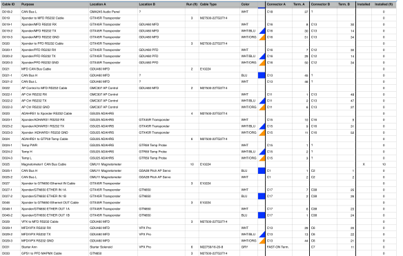
On to experiment #2. My TCW sensing circuit was on J12 pin 7, PFD on J8 pin 5 and misc Garmin equipment on J8 pin 1. I thought maybe it prioritizes by just starting from the lowest connector and pin so since I had J8 pin 2 open I temporarily moved the TCW sensing circuit from J12 Pin 7 to J8 pin 2 and like magic it worked perfectly. Not leaving well enough alone and also not wanting to use up a 10A circuit for a 5A load I then moved the TCW sensing circuit to J8 pin 7 which is a 5A circuit breaker. My thought was maybe if it’s all on the same connector the speed at which the VPX can turn off the circuits probably is negligible so it “should” still work. To my surprise though when I turned on the avionics switch the PFD rebooted which had never happened before. Turning off the avionics still worked fine. So now that leaves me with still a question of how the heck is this thing ordering the circuits. I’m thinking maybe it’s also taking into consideration the bank (The VPX Pro has 2 banks, A and B for redundancy) or maybe the breaker size, J8 pin 2 is a 10A circuit where J8 Pin 7 is a 5 A circuit so maybe it’s turning potentially high load circuits off first and on last. I’m hoping that their support can give me a good answer, but for now at least where I put the TCW sensing circuit seems to fix my issue.

Installing Rotax TLR 4.6 64-bit Software

TIP

So I thought it might be good to post something about installing and setting up the software that is available from Rotax for connecting the the 914 TCU. This is particularly for TLR46a 64-bit which probably most people will be using. The software itself is pretty easy to use, but there seems to be some issues when doing the installation. From the Rotax forum posts the people that do have issues look to be either moving to an older 32 bit system or reinstalling their OS to get it to work which didn’t make sense to me. It does seem that many people don’t have any issues, but then again if they don’t have issues then they’re not going to post anything so you don’t really know. I, of course was one of the lucky ones to have issues running the software on my Windows 10 laptop. So since I didn’t find a lot of “accurate” advice in the way of getting the software to work if you do have any issues I thought it might be helpful to someone if I posted what I did to get it to work and what I pieced together from a few places that I found some information.

Step 1: Figure out which software to download

First issue is you need to figure out what version of the TLR software you need to download. Most people doing a new aircraft build will most likely be using versions 4.6 which is for the newer TCU (part #966 741) which is printed in big letters on the front of the TCU case. Once you know the number of your TCU you can head over to the Rotax Owners site and go to the manuals section. Then click the headings “914 Software”. The other chose when using the 4.6 version is do you have a 32 bit system of a 64 bit system? If you’re using a PC or laptop from this century then it’s probably 64 bit. If you’re not sure then you can look at your PC properties and it will say under the “About” section. In windows 10 just open Settings and type “About”. Now you got the correct version of the software and got that downloaded.

Step 2: Get your USB to Serial adapter working

Next step, unless you’re using a desktop PC with a long straight thru serial cable then you’re probably going to use a laptop to connect to your engine TCU. Most laptops don’t have a real serial port so you need to get a USB to serial adapter which are very cheap now. One thing to be aware of though is a USB to serial adapter that uses the “Prolific” chipset will not work. I know first hand and also Rotax had a write-up about that had some details about using a USB to serial adapter with TLR and it mentioned that any adapter using that chipset will not work with the TCU. So when you plug in your adapter and if it has “prolific” in the name under Device Manager (I think you can see the chipset if you get properties on the device) then get yourself another adapter. The only other chipset I know of is FTDI so that’s what I searched on Amazon and got one for about $10. So now you have the correct USB to serial adapter and you just need to get the drivers installed for that. I just did a search on Google for FT232R and I downloaded the executable version of the VCP drivers for Windows. I tried installing the drivers through device manager and the USB Serial device still wasn’t working (yellow exclamation on the device name), but the executable version installed fine and the USB adapter looked good in teh Device Manager after the install. Now that you have a working COM port note the COM port number in device manager, mine was COM4 (as shown in the photo below) and you don’t need to change it like the TLR installation instructions say. That is only if you are using the 32 bit version of TLR.

Step 3: Install the TLR software

Now do the install of the TLR software which will put the software in C:\TLR64 and also install a program called DOS Box under the C:\Programs Files (x86) directory. This is where it gets a bit confusing and what seemed to break for me. The TLR program itself is 32 bit. If you try to run the executable on a 64 bit system it will just say the program won’t run on your system. Since Rotax is lazy and didn’t recompile TLR to run on 64 bit systems they used DOS Box as an emulator. TLR runs under DOS Box which is important to remember when you set up the COM port in TLR. The first time you run TLR it will pop up a selection box that you use to set the COM port mapping in DOS box. Then TLR starts and you select the video mode, and then the COM port to use, but the COM port you select in TLR doesn’t correspond to what the USB serial adapter is reporting in the Device Manager, it’s the COM port in DOS Box which then maps to an actual serial port on your PC.

What I found is that selection box that pops up when you first run the TLR software breaks DOS Box so when I ran TLR again it would just show “Error 68” in the DOS window. I’m sure you may get lucky and it will work, but it didn’t for me so this is what I did to get to get it working. After I ran the installer I when to the C:\Programs Files (x86)\DosBox_MB6 directory and double clicked the “dosbox” executable and then just quit it.

This creates a config file in your user directory under AppData\Local\Dosbox. You may need to select properties on you folder and enable “Show hidden files and folders”. Edit this config file.

You need to add in the DOSBox serial to PC COM port mapping and some auto execute lines so that it automatically launches TLR when you run DOS Box.

Find the “serial1=” and add in the mapping, your “real port” will be whatever shows for your USB adapter in device manager. Mine was COM4. Also remember that serial1 in DOSBox is COM1 in TLR so when you configure TLR use COM1. Are you confused yet?

There are a few lines that you need to add at the end of the file under the “autoexec” section of the config file as well. I copied these from the DOSBox config in the C:\TLR46 directory. And that show be all you need to change in your Dos Box config file.

Step 4: Setup TLR

With DOSBox configured you should now be able to run the TLR software (which runs DOS Box, which runs the TLR software) from the link on your Desktop. The first run will ask you to select a display mode (I selected “V” for VGA) and then the COM port to use. If you mapped your USB serial adapter to “serial1” in the DOSBox config file then select “1” for COM1. TLR should open and let you select options like the throttle calibration or monitor options. If it crashes with “Error 68” then something happened in the serial mapping or the DOSBox config got messed up. You can always run the dosbox executable again just to see if that runs OK, it will also report that it loaded the COM port so you can verify it’s starting up OK. Obviously you will get a Serial I/O error reported in TLR if you’re not connected to your TCU and the master switch isn’t turned on. To connect your USB serial adapter to the TCU you should be able to just connect the serial port on the adapter directly to the serial port of the TCU or you can also use a straight through serial cable if you need to extend it.

Well hope this helps if you had issues with the TLR software install.

Cheap GPS Repeater

When I was testing the G5, GNX and GDU GPS I didn’t get very good signal in the hangar (as to be expected). I found a GPS repeater on Amazon for around $14 and it seems to work very well. All antennas got multiple satellites and 3D differential fixes. The antenna and repeater have magnetic bottoms and it also comes with some double stick tape. I was able to just attach the antenna to the roof of the hangar with the magnet and the repeater to a metal box inside so no sticky tape was used. The wire between the antenna and repeats is very long, like 15ft and is detectable so you could use a different antenna if you need. Then from the repeater to the power source which is just a USB connector (no USB power supply is supplied though) is another 10 feet. I’m really happy with this thing. I’m thinking though that I’ll just keep it unplugged until need to use it just in case.

This is the GPS repeater I bought. Works great!

The Garmin 26C attached to the PFD seems to work.

And the GNX is happy as well.

Wing Dolly

Just a quick post about the wing dolly I made. Not quite ready to put the wings on it though. I used some plans I found on a Google search off the EAA website. I modified the length of end posts a bit because I may end up storing the wings with the tanks off for now, until I get all the parts to build them.

Here’s the plans I found. I also used metal brackets instead of the wood braces because I’m just lazy. I did use one wood brace for the uprights to the cross pieces. I got the wood from the cover to the shipping crate the spars came in.

I also used one set of steerable casters and another that are fixed so I can pitot the dolly around. The handle is on the side that steers.

I think in all it cost me about $75 to build the dolly, but I had a few 2×4’s already. The most expensive part was the tow strap which was around $20.

Some photos of the finished dolly. I still need to determine the length of the straps, but will do that when I have a wing to put on it. Not quite ready yet to do that.

Engine Ordered

Not much to report on the plane except I finally plunked down the cash and got the engine order. So I guess no new car for me, mine will just have to hold out for a few more years. I ended up ordering the 914UL2 from TAF and it should be here in a few weeks. Now of course Rotax will cut the prices… just my luck. Anyways it’s good to know I’ll be able to start making some progress on the plane soon.

Oh yeah. While I was there Jean and I tested out their new ordering system. I think it’s going to be pretty cool. Basically you just sign into the website and order whatever parts you want by part number. You can also choose whether it’s to replace a missing part or a new part, etc and then they ship it to you. It looks like shipments go out once a month towards the end of the month so it will still take some time to get them, but should be much easier to get the parts.


Mold for Throttle Console

Started on the making of the mold for the throttle console. I’ll do the gel coat and fiber glass backing tomorrow. Hopefully all goes well and I can get the mold down to the carbon fiber guy next week and have the parts by the end of the year.

Plug ready to go, just need some waxing and mold release.

Mold Redux

I’ve actually had this done for a week or so, but forgot to post it. I made a mold for the carbon fiber glove box top that I want to make. I’ll take this down to the guy that’s going to make the part to see if this will work. If it looks good then I’ll make one for the throttle console as well. The mold came out OK, but its not a glossy as I thought it would be and I had some issues with getting the gel coat to the correct thickness. This is supposed to be really good gel coat, but for some reason I’m having a lot of problems with it. The manufacture says it needs to be sprayed, but I see a lot of other people brushing on the gel coat and it seems to come out really nice. I’ll have to look around to see if I can find another manufacture for the gel coat.

Part is ready to go. I filled all the holes with expose resin and sanded them flat.I greatly simplified the mold prep from the last time and also used a lot less wax on the seams.

Gel coat not going on so well

I was able to get a second coat on without it bubbling, but still not great.

Used some epoxy resin and talc to reinforce the corners

Two coat of resin and fiber mat. Now I need to add the wood bracing.

Wood bracing is in and now just need to add another 3-4 layers of mat. This makes a sizable mess.

Finished mold. It came out OK. I was hoping it would be a bit more glossy for a better finish on the final part. I think I can polish it so I need to look into that.


The Making of a Mold

I tried my hand at making a mold of the “glove box” top so that I can have someone make a carbon fiber copy of it. Well it didn’t come out terrible, but it didn’t come out great either. Probably not good enough to use for the infusion process. A few things I learned and need to do different. First I used polyester epoxy gel coat which is better then the regular epoxy gel coat, however this stuff really needs to be sprayed on rather then brushed on. Since I don’t want to spend a bunch of money on a spray, I think I’ll try regular epoxy gel coat which I believe is a bit more forgiving when brushed on. I tried to use Bondo as a backing for the mold, but it’s still too flexible. I suppose I could use a lot more and a build up a thicker mold, but I really don’t like the process of using the Bondo anyways so I’ll just abort this idea and use the layered fiberglass and resin method instead. The last thing is that I covered the part with 3M wrap to hide the holes, but the gel coat gets so hot that it softened the wrap and the holes still showed through so I’ll instead fill the holes with epoxy or something.


The mold ready for the mold release then gel coat.


Sprayed the mold release onto the mold. I need a better sprayer though. It supposed to just be misted on, this spray got it a bit too wet.


Well I forgot to take a photo after I put on the gel coat… probably because I was frustrated that it didn’t go on so well. When that got tacky I put on the Bondo. Looks like a tasty cake, but doesn’t smell so good.


I let that all dry over night and inn the morning after carefully prying it free from the board and other mold parts this is what I ended up with. You can see that the 3M wrap didn’t work so well because the holes are still quite visible. The mold also cracked a little when I was prying it off because the bondo was too flexible. Overall though it didn’t come out too bad. I was hoping to get it right on the first try, but I think the second will be the one. I need to order some epoxy gel coat and I’ll try again.

Carbon Fiber Parts

It’s been bugging me that some of the parts in the Sling interior are a sticker that looks like Carbon Fiber. The sticker eventually rubs off, especially on the throttle console. I believe 3M also makes a better Carbon Fiber covering, but still it’s a covering. I’ve been doing some research and am going to attempt to first make a mold of the throttle and glove box covers. From these moulds I should be able to either make a carbon fiber replica or have someone do it for me. The instrument panel is somewhat straight forward since it’s just a flat piece and then needs to be CNC’d

From what I’ve found about making the mould is that you use a release agent (PVA and Parting Wax) on the part (called the plug) and coat it with a gel coat resin (and MKEP hardener) that you brush (or spray) onto the part. This forms a negative or positive mould depending on how you mould the part. You then cover the gel coat with layers of chopped strand mat to build up some rigidity of the mould. Fiber Glast has a good tutorial of the process and there are a few videos on YouTube. You can also use an epoxy putty or Bondo to form the rigid part of the mould if you like. It really depends on how big the part is, the shape and how durable a mould you need. It’s got me intrigued enough to want to see if I can at least make a mould of the two parts.

I ordered the following from Amazon

  • Creativity Street Modeling Dough, Blue, 3.3-lb. Tub (AC4070)
  • Fibre Glast FibRelease
  • Fibre Glast Orange Tooling Gel Coat – Quart w/ hardener

The creative dough is a filler so that the gel coat doesn’t seep through holes and cracks in the plug. I’ve seen people using the Pelikan Nakiplast modeling clay, but it’s around $30, so I figured I’d give this other one a try. The FibRelease is a new way of coating the plug instead of using both the PVA and parting wax.

On another note I found this cool 3D CNC machine for around $1600 called XCarve from Inventables. Theres a 500, 750, and 1000mm wide version and also more parts where you can expand it even larger. It uses free software called Easel to create and sending it to the CNC machine. I suppose if I were going to make more parts for the plane then this might come in handy but right now the only thing I’d use for is cutting the panel which I can probably do cheaper then $1600, but still very cool and Christmas isn’t too far away so maybe, just maybe I might get one.

I should be the materials in a week so I’ll post my success or failure on the blog. If the moulds come out good and I can find someone to do the Carbon Fiber then I’d be happy to offer the use to the builders who might want to do the same. I can’t say it’s going to b really cheap, but probably fairly reasonable.


Wire Run Spreadsheet

I’ve been trying to organize the wiring for the project. I had previously created an Excel Spreadsheet (Well I actually use Apple Numbers) which I uploaded in the Links section of this site, but I didn’t have a way to detail individual cable runs inside a multicore cable (like an M27500 cable). Also I really didn’t have any way to identify connectors and the pins that the wires come up on. I’ve added these things to the spreadsheet, but it’s a pretty manual process to build the sheet with the connector pinouts. I have to copy and paste for the main spreadsheet to the connector pins one. Maybe if I used Excel there would be an automatic way to do it. I had found a really nice piece of software called RapidHarness which lets you pit together wire harnesses and is fairly detailed in how you can show the cables and connectors. They offer a free version which only allows for 30 connections. If you want to go beyond that (I think to 500) it costs $200/month. So well that’s just a bit too pricy for me so I guess my spreadsheet will have to do. I’ll upload a copy when I have it all updated, but here’s a few screen shots of what I’ve been trying to do.

This is the main wire run list. I added the Connector A and Connector B column as well as the wire color image… well it’s not really an image it’s a background gradient for the multi-color wires and just a background color for the solid color cables. I was trying to find a way to set this field automatically based on the “color” cell, but can’t quite seem to figure that out. Maybe if I use an actual image I could use a calculation field to set it… HMMM

I Added another table with the list of connectors and some info about them. I was thinking that maybe I should call the ones that have a named mating connector the same as that connector. So instead of calling the connector C1 call it something like C111-1 in case you have more then one. I will probably want to label the physical connector in the airplane with this label so that it’s more easily identified in the future. Like if changes are needed to be made to the connector I can look in the spreadsheet and see how it’s wired.

This is the new sheet that basically takes the Connector A/Term A columns and Connector B/Term B column and combines them into one table. This needs to be done because sometimes a connector may be referenced under Connector A or ConnectorB and we want to know all the occurrences of it so we have all the wires/pins that are in the connector. Build this table is manual so if anything changes in the main wire list then I have to rebuild it…. which sucks. I do like the wire color icon column… it makes it look pretty cool and is actually really useful in finding stuff.