Time: 1 hr
HAPPY NEW YEAR!!!!!
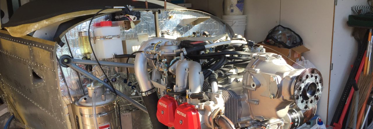
Today I mounted the fuel pump box to the firewall and installed the pins (provided by Rotax) for the A & B ignition switches.
I decided to use the fuel pump box that comes with the Rotax 912 instead of the one that TAF provides. I’m pretty sure that the the connecting hoses that TAF uses and check valves “should” all fit in the box. To mount the box I purchased 4 stainless steel M6 double sided bolds to mount it to the firewall. I also made a gasket out of some silicone I had around. There were a few extra holes in the firewall that I didn’t use and I just wanted to make sure they were sealed up.
For the ignition switch wires I used a shielded 18 AWG wire (as per the Rotax manual). I was going to run 2 single shielded wires, but saw in an RV12 manual that they used a 2 conductor 18 AWG shielded cable which seemed like a cleaner way to do it. I also utilized the existing metal clamp which is well grounded to ground the engine side of the cable braid. The switch side will also be grounded. I typically only have been grounding one side of the shield but in this case it may be beneficial to ground both sides.
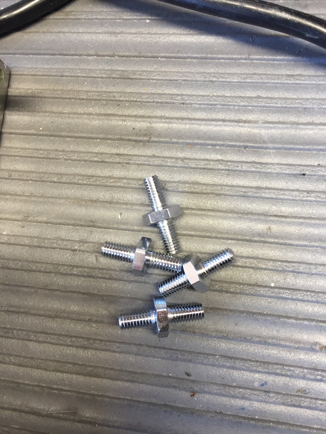
Stainless steel M6 double sided bolts I found at SIMWorks. The nut allows the bolts to be easily tightened, but also serve as a stand off so I can mount an aluminum plate I made that the pumps will mount to. The space provides room for a bolt head to mount the adel clamps that will hold the pumps. The whole plate can be easily removed so the pumps can be serviced. I don’t want to mount the pumps until I get the plumbing from TAF for connecting the pumps together.
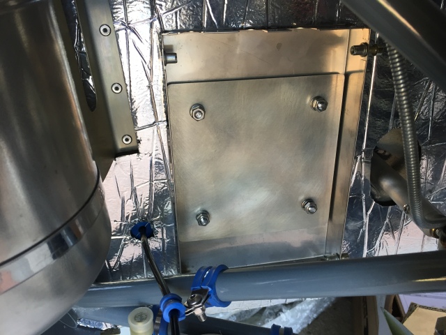
Fuel pump box mounted and test fit the aluminum plate that the pumps will be mounted to. I will be drilling a hole to run the fuel pump power and ground wires. I’m thinking maybe a few inches above the box and to the left, but will have to look at it a bit more.. One wire will run into the top and one will wrap around into the bottom for the second pump.

Crimped the flat pin onto the 18 AWG wire. The pin is provided by Rotax. Now that I look at it I wonder if the rubber sealing grommet should have been part of the crimp. I think it should be, but it did fit very tight into the connector so it should stay in there fine. If I notice it coming out after some flight time then I can always re-crimp the pin since I have a few extras. The other side of the connection mates with a brown wire. This is done for ignition module A and B. BTW These are the horizontal mounted connectors, there are also two connectors the are mounted vertical that have an open hole so you need to make sure to connect the wires to the correct connector.
I also cut back the outer jacket on the wire so that the braid was exposed enough to touch the metal clamp. The clamp even has its own ground wire, so it should be a good ground point for the braid.
NOTE (1/6/2019): I ended up fixing the rubber seal so that the seal was part of the crimp on the sheathing. It took some time to figure out how to get the pin out of the connector though. To do this you remove the pin from the pin side of the connector. There is a small square area above each of the pins so I just uses a very small flat bladed screw driver to push in that square area and lift up on the small tab. The tab fits down into a cut out on the pin so by lifting that it allows the pin to be pulled back out.
